MICROBIOLOGY - M.H. Serhiichuk - 2008
Chapter 2. MORPHOLOGY AND STRUCTURE OF THE BACTERIAL CELL
Methods for Microscopic Examination of Microorganisms
The primary instrument for studying The Structure of a bacterial Cell is the microscope. A Light Microscope is a complex optical device designed to examine small objects, organisms, and tissue structures—that is, objects invisible to the naked eye. Modern microscopes make it possible to study objects using light rays passing through a system of lenses and the specimen, as well as to perform phase-contrast, fluorescence, Interference-polarization, and Other types of microscopic examination.
The main Structural components of light microscopes include the mechanical and optical parts, along with the illumination system (Fig. 2.1).
Class="center">
Fig. 2.1. Microscope with a binocular HEAD and mirror:
1 - eyepieces; 2 - binocular head; 3 - revolving nosepiece; 4 - objective lens; 5 - stage; 6 - condenser; 7 - mirror; 8 - condenser bracket adjustment knob; 9 - fine focus knob; 10 - coarse focus knob; 11 - limb (body tube arm); 12 - head locking screw
Modern objective lenses are multi-lens systems (Fig. 2.2) upon which the quality of the image depends. The arrangement of lenses within the objectives is such that only the tiny lens facing the specimen (the so-called front lens) produces a real magnification. All other lenses are corrective, serving to compensate for aberrations inherent in optical systems. The more powerful the objective, the shorter the focal length of its front lens; consequently, as magnification increases, the lens takes on a more spherical shape. The smaller the front lens, the higher the resolving and magnifying power of the objective.
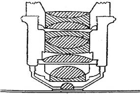
Fig. 2.2. Objective lens consisting of 10 lenses
One of the drawbacks of optical systems is aberration. Aberrations are classified into chromatic and spherical. Chromatic aberration occurs when the image formed by green rays does not coincide with the image formed by red and blue rays, resulting in a colored outline around a colorless object. Spherical aberration manifests when a point of the object is projected not as a point, but as a circle of varying diameter. As a result, the image becomes blurred and indistinct because the field of view is curved, making it impossible to focus simultaneously on the center and the edges of the object's image.
The Main characteristics of a microscope objective are its magnification and aperture. The resolving power of an optical microscope depends on the objective aperture. The aperture (A - numerical aperture) of an objective is the sine of half the aperture angle (sin α/2) at the vertex of the light cone passing through the object (Fig. 2.3): A = sin α /2 .

Fig. 2.3. Ray tracing diagram for different values of angle u:
A - object; O - objective; α - aperture angle ; u - half of the aperture angle
This equation holds true if air (n = 1) is present between the object and the front lens of the objective. To increase the objective aperture, it has been proposed to fill the space between the front lens
of the objective and the object with a substance having n > 1, in which case: A = n sin α/2. Such substances are called immersion media. They were first introduced by Giovanni Amati in 1840. In recent years, objectives requiring various immersion media have been manufactured (Table 2.1).
Table 2.1. Refractive indices of various media
Substance |
Refractive index |
Achieved aperture |
1.33302 |
1.25 |
|
Glycerin |
1.47158 |
1.35 |
Cedar oil |
1.51525 |
1.40 |
Monobromonaphthalene |
1.65820 |
1.60 |
An eyepiece typically consists of two lenses: one facing the object and the other facing the eye. The choice of eyepieces for work depends on the type of objective being used. Eyepieces differ in magnification and design.
The illumination system of an optical microscope consists of a condenser, a mirror, and a light source. It is designed to provide optimal specimen illumination. The condenser is mounted above the mirror and consists of several lenses. It collects parallel rays reflected by the mirror from the light source into a single point—the focus, which should lie within the plane of the specimen. The condenser, along with its mount, can be vertically adjusted within 20 mm using a dedicated screw. The mirror, concave on one side and flat on the other, is mounted in the microscope base. When working with a condenser designed for focusing parallel light beams, only the flat side is used. The concave mirror is used when working without a condenser. In this case, the mirror collects the bundle of parallel rays coming from the light source and focuses it in the specimen plane.
In most modern microscopes, the illumination system is built directly into the microscope itself.
The resolving power of an optical microscope is the shortest distance between two points (or lines) at which they can be distinguished as separate entities (without merging). This characteristic depends on the numerical aperture of the objective (A1), the microscope illumination system (A2), and the wavelength of light (λ):

The wavelength of light perceived by the human eye is 0.4–0.7 µm (with an average λ of 0.55 µm).
As shown by the equation, the resolving power of a microscope increases as the wavelength of the light used to illuminate the object decreases, and as the numerical aperture of both the objective lens and the illumination system increases.
Ultraviolet rays have the shortest wavelength—half that of daylight. Based on this principle, P. Köhler and R. Rohr designed an ultraviolet microscope. Since ordinary Glass is almost opaque to such rays (λ - 0.4 µm), the microscope lenses had to be made of quartz and fluorite. The invisible image is captured using a photographic plate.
A different concept underlies the ultramicroscope developed by Zsigmondy and Siedentopf. It is a well-known phenomenon that tiny dust particles in the air become visible in a dark room when a side beam of light passes through a small aperture. Building on these observations, they applied THE PRINCIPLE OF powerful dark-field side illumination. This type of illumination clearly highlights the brightly lit contours of the object against a dark Background, increasing resolving power by one or more orders of magnitude.
Decreasing the wavelength of light minimizes distortions in the fine structures of an object caused by diffraction phenomena.
Increasing the numerical aperture of the objective lens makes it possible to collect rays scattered at wide angles by the minute details of the object.
Thus, the resolving power of a microscope can be enhanced by decreasing the wavelength of the light passing through it (such as by using blue light filters) and by increasing the aperture of The Optical System.
The total magnification of a microscope (V) is determined by multiplying the magnification of the objective lens (Vоб.) by the magnification of the eyepiece (Vок): V = Vоб · Vок . If the objective provides 100х magnification and the eyepiece 15х, the total magnification is 1500. To fully utilize the resolving power of the microscope and achieve the best possible visualization, it is essential to use the optimal combination of objective and eyepiece that yields the so-called useful magnification. It has been established that the useful magnification of a microscope cannot exceed the numerical aperture of the objective by more than 1,000 times. Based on this useful magnification, an eyepiece is selected that best matches the given objective.
Overall, in bright-field Microscopy, the resolving power of a modern optical microscope is 0.2 µm.
Dark-field microscopy is based on the Tyndall effect—illuminating the object with oblique, high-aperture side rays of light. This is achieved using specialized parabolic condensers, dark-field condensers, or a standard Abbe condenser with an obscured central stop. In such condensers, the central part of the parallel beam is blocked and prevented from entering the objective lens. The field of view remains dark and unilluminated. The peripheral rays pass through the annular slit of the condenser, located between its central part and the edge, strike the lateral surface of the lens, are reflected from it, and are directed at an angle into the plane of the specimen to be focused upon it. If there are no particles in the path of the oblique reflected beam, it refracts and exits beyond the plane of the specimen without entering the objective (Fig. 2.4). The field of view remains dark.

Fig. 2.4. Beam path in dark-field microscopy:
об. - objective lens; п. - coverslip; п.с. - microscope slide; о. і. - oil immersion; д.т. - dark-field Diaphragm; л.к. - condenser lens
If the specimen contains any particles (objects), the oblique rays reflected by the condenser encounter these particles and are diffracted by them, producing diffracted light waves. These diffracted rays propagate at various angles, and a fraction of them enters the objective lens. As a result, brightly glowing particles become visible against the dark background of the field of view.
For dark-field examination, specimens are prepared using the " hanging drop" method (the slide must be no more than 1.1 mm thick, and the coverslip 0.17 mm thick).
Dark-field microscopy is classified among ultramicroscopic Methods because of its higher resolving power (up to 0.06–0.02 µm). It allows researchers to observe the motility of microbial Cells, detect the causative agents of certain diseases (such as leptospirosis), and study microorganisms whose dimensions lie beyond the resolution limit of a standard light microscope. However, dark-field microscopy does not allow for a detailed study of cell Morphology, particularly internal structures.
Phase-contrast microscopy. The human eye distinguishes only the wavelength (color) and amplitude (intensity, contrast) of a light wave, but is insensitive to phase differences.
Almost all living cells are transparent because light rays passing through them do not alter their amplitude. However, image contrast is known to be directly proportional to the degree of Light absorption by different Structural elements of an object. If an object consists of alternating areas with high and low light absorption, the light passing through these different areas will be altered accordingly. A "phase" (low-contrast) specimen can be converted into an "amplitude" (high-contrast) specimen either by staining (which is largely unsuitable for living cells) or by decreasing the condenser aperture—closing its iris diaphragm—though this reduces the resolving power of the microscope.
Phase-contrast microscopy was developed specifically for observing transparent specimens. It is based on converting the phase shifts—which occur when light waves pass through an object—into visible amplitude changes using a specialized optical device (Fig. 2.5).

Fig. 2.5. Beam path in a phase-contrast microscope
If a special disk—a phase plate with a ring (produced by sputtering heavy metal salts onto a disk to a thickness of several tenths of a micrometer)—is integrated into the objective lens of a standard microscope, and an annular diaphragm (an opaque plate with a transparent ring-shaped slit) is placed in the condenser such that only a ring of light passes through the condenser and objective to align with the phase plate ring, the Phases of the transmitted light are shifted (typically by 1/4 of a wavelength). This converts phase variations into amplitude variations, rendering the specimen contrast-enhanced. Specimens that appear transparent in a bright field become sharply contrasted against a bright background (positive phase contrast) or brilliantly glowing against a dark background (negative phase contrast).
A light beam striking a transparent object splits into two components: direct and diffracted beams. The direct beam A (see Fig. 2.5) emerges from the annular diaphragm, passes through the object's structures, and focuses on the phase plate ring. The diffracted beam B passes through the object and misses the phase plate. The optical paths of these two beams differ, creating a phase difference that is imperceptible to the unaided eye. The phase plate then converts these phase shifts into amplitude variations that can be perceived by the eye.
Phase-contrast microscopy does not increase the resolving power of the microscope's optical system, but it enables the examination of the fine structures of living microbial cells, The Study of their developmental stages and Cell Division processes, the assessment of chemical effects on microbial cells, and the measurement of their dimensions in vivo.
Fluorescence Microscopy. Ernst Abbe's concept of utilizing ultraviolet light to enhance microscope resolution was realized in 1904 by Carl Zeiss researchers P. Köhler and M. Rohr during The Development of the fluorescence microscope. The image in a fluorescence microscope is formed by the emission of light (fluorescence) from the specimen when illuminated by short-wavelength rays (λ = 300–460 nm).
Luminescence refers to The phenomenon of light emission by excited systems—that is, systems formed as a result of the absorption of Various Forms of energy by the constituent atoms of a substance. Depending on the type of energy absorbed, a distinction is made between thermoluminescence, chemiluminescence, electroluminescence, and photoluminescence.
Photoluminescence is luminescence that occurs following the preliminary absorption of light quanta. A particle begins to emit intense Light as a result of absorbing quanta of the exciting light. Upon returning to its ground state, the system releases the acquired energy in the form of light, the wavelength of which is greater than that of the exciting radiation.
Radiation quantum energy is inversely proportional to wavelength; therefore, the quanta of exciting radiation always contain more energy than the quanta of luminescent emission.
In the luminescence phenomenon, a certain time interval elapses between the absorption of the excitation energy and the emission of the luminescent light. If this time interval exceeds 10-4 s, the phenomenon is called phosphorescence; emission occurring over a shorter time interval is termed fluorescence. The emission from the substance of the object itself when irradiated with ultraviolet rays is called primary fluorescence or autofluorescence (intrinsic fluorescence). Conversely, if the emission originates from a special substance (so-called fluorochromes) with which the test object is impregnated, it is referred to as secondary fluorescence. During fluorescence, objects such as cells appear to glow against the dark background of the microscope's field of view.
Preparations treated with fluorochromes emit light in media that do not exhibit luminescence under short-wave radiation, such as water, glycerin, liquid paraffin, or saline solution.
Luminescent microscopy makes it possible to observe objects whose dimensions lie beyond the resolution limit of an optical microscope. Furthermore, it enables the study of changes in individual cellular structures across various functional states.
Electron microscopy. One of the significant achievements of 20th-century applied physics was the invention of the Electron microscope, which revolutionized scientific understanding of biological structures. The principle of electron microscopy is that an electromagnetic field affects a beam of electrons in a manner analogous to how a glass lens affects a ray of light. An electron beam is characterized by The properties of electromagnetic radiation with a very short wavelength. If electrons are accelerated in an electric field with a voltage of 100 kV, the wavelength is only 0.04 nm—approximately 10,000 times shorter than that of visible light. Consequently, the resolving power of an electron microscope is several orders of magnitude higher than that of a bright-field microscope (see the equation for optical microscope resolution).
The path of electrons in a transmission electron microscope (TEM) is similar to the path of visible light rays in a light microscope. A beam of electrons emerging from the electron gun passes through a series of electromagnetic lenses. The condenser lens focuses the electron beam onto the specimen, while a set of magnifying lenses creates an enlarged image that is projected onto a screen. Since
air would obstruct the movement of electrons, the entire path of the electron beam is maintained under high vacuum. Due to the low penetration depth of electrons, electron microscopy is restricted to examining ultrathin sections up to 100 nm thick.
In a transmission electron microscope, contrast arises from the differential scattering of electrons across various areas of the specimen, with scattering efficiency depending on the atomic number and mass of the atoms. Because biological Materials are composed predominantly of low-mass atoms, the inherent contrast of such materials is low. It is enhanced by coating the specimen with heavy metal salts.
Both light and transmission electron microscopes produce a two-dimensional image. A modified electron microscope (Scanning electron microscope, or SEM) makes it possible to obtain a three-dimensional image of The surface of studied objects. In such a microscope, the object—coated with a thin layer of a heavy metal—is scanned by a narrow beam of electrons (an electron probe) much like the raster in a television tube. Electrons originating from the specific point on the object struck by the scanning beam are collected by a detector, and an image is generated on a cathode-ray tube screen via an amplifier. Contrast is determined by the fact that the number of secondary electrons reflected by the object is proportional to the angle between the electron beam and the object's surface, thereby revealing its Spatial Structure.
Last update: 13/08/2026
Editorial and Educational Adaptation: This material has been compiled based on the primary/original source text. The project team performed an editorial review, corrected technical inaccuracies, structured sections, and adapted the content for an educational format.
What was processed:
- elimination of formatting defects (OCR errors, structural breaks, corrupted characters);
- editorial organization of content;
- standardization of terminology in accordance with academic sources;
- verification of factual statements against the original source text.
All mentions of the author, publication year, and origin of the primary text have been preserved in accordance with the source.