BIOTECHNOLOGY - V. H. Gerasymenko - 2006
Part II. Special Biotechnologies
Chapter 22. BIOTECHNOLOGIES FOR WASTE UTILIZATION AND BIORECYCLING IN THE AGRO-INDUSTRIAL COMPLEX
22.3. NON-TRADITIONAL METHODS. BIOTECHNOLOGY FOR BIOGAS PRODUCTION VIA ANAEROBIC DIGESTION OF WASTE
22.3.3. Technical and technological aspects of biogas production
22.3.3.4. Technical and technological levels of biogas plants (BGPs)
Existing BGPs vary significantly in their structural design, equipment, configuration, operating principles, biomethanogenesis process parameters, and productivity. Taking this into account, four distinct levels of BGPs can be classified.
Level 1 BGPs. This represents the simplest technical tier. Such systems are typically used in regions with tropical climates, where the methane digester and gas holder are combined and usually buried in the ground. The biomass being digested is neither heated nor mixed, and there is no regulation or control over the anaerobic Digestion process. Biogas production takes 40 days or more. The "Gabor" plant, operated in China and India, belongs to this technical level. Its productivity is 1.7 m3 of biogas per day and 0.2-0.5 m3 per 1 m3 of the Fermentation chamber volume.
In Cuba, a BGP has been developed and operated in the form of an anaerobic lagoon hermetically sealed with a polyethylene film, equipped with Valves for biogas extraction. Once the biomethanogenesis process is complete, microalgae can be cultivated in the remaining sludge.
In Western Europe, for instance in Romania and Italy, simple small-scale BGPs with a Reactor volume of 6-12 m3 have been widely used for over 20 years in individual homesteads. The structural and technological layouts of such biogas plants are shown in Fig. 22.3. The arrows indicate the Processing flows of the initial organic mass, gas, and sludge. These installations essentially consist of a pit lined with brick or reinforced concrete slabs, plastered with cement mortar, and coated with tar for airtightness (Fig. 22.3, a) or covered with securely welded sheet iron (Fig. 22.3, c). A dome made of painted sheet iron (rigid) or polyethylene film is placed on top of the pit, with a nozzle installed at the upper part for biogas extraction. A Water seal—a concrete groove up to 1 m deep filled with water, into which the lower rim of the dome is submerged by 0.5 m—is constructed around the fermentation pit.
The gas collected under the dome or film flows through a gas pipeline to the point of use. To prevent gas explosions, it is recommended to install a pressure-regulated valve on the exhaust pipe. However, the risk of explosion is low because if the gas pressure under the dome rises significantly, the dome will rise in the water seal to a critical height and tip over, releasing the gas safely. Biogas production can decrease due to The formation of a crust On the surface of the organic substrate inside the fermenter during digestion. To prevent this crust from obstructing biogas release, it is broken up by mixing the biomass within the fermenter. For this purpose, a metal fork can be attached to the underside of the dome. As biogas accumulates, the dome rises to a certain height in the water seal and descends as the gas is consumed. Through this systematic upward and downward movement, the attached forks break up the crust.
A BGP with biomass heating utilizing the heat generated from manure decomposition in an aerobic fermenter has also been developed (Fig. 22.4). It includes a cylindrical metal fermenter equipped with a charging neck, a drain valve, a mechanical stirrer, and a biogas outlet nozzle. A rectangular fermenter made of collapsible wooden structures is located outside the reactor to facilitate the unloading of spent manure. The floor of the fermenter is lattice-based, allowing air to be blown through the process channel so that the manure is actively aerated. The top of the fermenter is closed with wooden panels. To reduce heat loss, the walls and bottom are designed with a thermal insulation layer.
Class="center">
Fig. 22.3. Schematics of simplified biogas plants:
A — with a pyramidal dome: 1 — manure pit; 2 — water-seal groove; 3 — gas collection dome; 4, 5 — gas outlet nozzle; 6 — pressure gauge. B — condensate removal device: 1 — gas pipeline; 2 — U-shaped condensate pipe; 3 — condensate. C — with a conical dome: 1 — manure pit; 2 — dome; 3 — expanded nozzle section; 4 — gas outlet pipe; 5 — water-seal groove. D-G — alternative layouts of simplified plants: 1 — organic waste supply; 2 — organic waste container; 3 — gas accumulation area under the dome; 4 — gas outlet nozzle; 5 — sludge discharge; 6 — pressure gauge; 7 — polyethylene film dome; 8 — water seal; 9 — load/weight; 10 — seamless polyethylene bag

Fig. 22.4. Schematic of a heated biogas plant:
1 — fermenter; 2 — wooden panel; 3 — charging neck; 4 — methane digester; 5 — stirrer; 6 — biogas extraction nozzle;
7 — thermal insulation layer; 8 — grate; 9 — drain valve for processed biomass; 10 — air supply channel; 11 — blower
The plant operates as follows: pre-prepared liquid manure with a moisture content of 88-92% is poured into the methane digester through the neck. The aerobic fermenter is filled from the top with bedding manure or a mixture of manure and a loose dry organic filler (straw, sawdust) with a moisture content of 65-69%. When air is supplied through the technological channel, the organic mass in the fermenter begins to decompose and generates heat, which warms the biomass in the reactor. The resulting biogas accumulates in the upper part of the methane digester and is drawn off via a nozzle for household use. Such an installation pays for itself within a year solely through waste utilization on a household farm.
The greenhouse effect is also utilized to heat the fermenter. A metal frame is erected over the vessel (reactor) and covered with a polyethylene film. In adverse weather conditions, it retains heat and significantly accelerates the decomposition of the raw Materials. To ensure optimal conditions for biomethanogenesis, the manure can be mixed with hot water (if moisture levels permit).
In the former Soviet Union, an individual biogas plant (IBGP-1) was developed for a peasant family owning 2 to 6 cows, 20 to 60 pigs, or 100 to 300 poultry (Fig. 22.5). The unit can daily process from 100 to 300 kg of manure and produce 3-12 m3 of biogas. Cooking meals for a family of 3-4 people requires burning 3-4 m3 of biogas per day, while heating a 50-60 m2 house requires 10-11 m3 of biogas. The plant can operate in any climatic zone. Serial production of the IBGP-1 was established at factories in the cities of Tula and Oryol.

Fig. 22.5. Schematic of the IBGP-1 individual biogas plant:
1 — charging neck; 2 — stirrer; 3 — gas extraction nozzle;
4 — thermal insulation layer; 5 — discharge pipe with a valve for processed mass; 6 — thermometer
The presented structural and technological designs of the simplest biogas plants can be used year-round in the southern regions of Ukraine and seasonally in other oblasts.
Second-level BGPs are more productive and cost-effective. They feature heating and mixing of the biomass undergoing fermentation, as well as grinding when necessary. An example of this type is the Darmstadt model. It yields four times more biogas per 1 m3 of digester volume than the Gabor BGP, specifically 1.2–2 m3. However, the plant has structural drawbacks: insufficient thermal and waterproofing due to the reactor being buried in the ground, the potential formation of stagnant zones during biomass mixing, and additional energy consumption required to break up the floating crust that forms across the entire surface of the fermentation chamber as biogas is released.
Third-level BGPs. These are plants manufactured in Germany: Lipp, Reike, Bima, MBB; domestic ones — Kobos-1, Biogas-301, UkrNDIagroproekt; Enbom — Finland, etc. (Fig. 22.6). They incorporate structural modifications, such as a dual-chamber reactor and, in some cases, a dual-chamber gas holder. This enables a two-stage methane fermentation of the biomass: The First stage encompasses the First and Second steps of biomethanogenesis, namely the fermentation of organic matter into acetate in the first chamber, and the Second Stage involves actual methane fermentation In the second chamber.
Furthermore, the design of German BGPs (Lipp, Reike, MBB, Bima) provides for different Temperature regimes in the respective chambers. The first chamber, where the pre-warmed biomass prepared for fermentation enters and where organic acids are formed, is maintained at a temperature of 35 oC. The second chamber, located in the center of the digester, undergoes a thermophilic process. Such structural improvements have increased the productivity of biogas plants, yielding 7 m3 of biogas per 1 m3 of the reactor's useful volume.
The domestic Kobos-1 BGP is a set of equipment designed for the anaerobic digestion of manure to produce commercial biogas and highly nutritious organic fertilizers. It consists of a reactor, a preheater-holding tank, a gas holder, pumps, a compressor, and a water-heating boiler (Fig. 22.7).

Fig. 22.6. Various types of biogas plants currently in operation in Germany:
a — Bima; b — Lipp; c — flexible reactors; d — general view of biogas production; e — Darmstadt
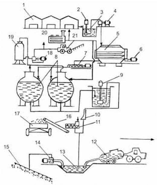
Fig. 22.7. Technological flow diagram of the Kobos-1 equipment complex
(after L.V. Pohorilyi, M.M. Lutsenko, 1992):
1 — farm; 2 — slurry pump; 3 — manifold; 4 — grinder; 5 — preheater-holding tank; 6, 9 — manure pumps; 7 — screw pump; 8 — reactors; 10 — curved screen; 11 — filter press; 12 — spreader tanker; 13 — manure storage; 14 — pump; 15 — irrigation system; 16 — conveyor; 17 — cart; 18 — compressor; 19 — gas holder;
20 — boiler; 21 — biogas-powered tractor
Kobos-1 is designed for cattle farms and complexes with a capacity of 400 HEAD or 4,000 pigs, featuring two reactors with a capacity of 125 m3 each. For complexes with 600 and 800 head, the number of reactors is increased. The BGP design provides for two-stage methane fermentation.
Manure from the farm is fed into a grinder, where long-fiber impurities (straw, tops) are broken down, and then pumped into the first chamber — a preheater-holding tank with a capacity of 25 m3. This is a cylindrical reservoir equipped with a heat exchanger based on a closed "tube-in-tube" system, where the manure is heated to a temperature of 40 oC. In this chamber, high-molecular-weight compounds undergo Hydrolysis into low-molecular-weight compounds, resulting in the formation of organic acids, carbon dioxide, ammonia, etc. From the preheater-holding tank, a dosing pump periodically feeds the manure (4 times a day) into the reactor, where the final conversion of organic matter into biogas takes place.
Maintaining the required mesophilic temperature (+40 oC) at a constant level and compensating for heat losses in the reactors and chamber are achieved using heat exchange devices through which hot water (70 oC), obtained by burning biogas, is supplied.
In terms of its main Qualitative and quantitative indicators, Kobos-1 is on par with foreign analogs, and even holds advantages in parameters such as processed mass productivity, biogas yield, and fermentation duration (5 days).
The Biogas-301 plant (Sumy Machine-Building NPO) is designed for the utilization and disinfection of waste from farms with a livestock population of 3,000 pigs. It operates as an integral part of the farm. The technological process is carried out under specific anaerobic conditions in a two-stage mode at a temperature of 40 oC with an 8-day fermentation cycle.
Fourth-level BGPs. These plants feature automated computer-programmed control of the anaerobic digestion process.
Last update: 11/08/2026
Editorial and Educational Adaptation: This material has been compiled based on the primary/original source text. The project team performed an editorial review, corrected technical inaccuracies, structured sections, and adapted the content for an educational format.
What was processed:
- elimination of formatting defects (OCR errors, structural breaks, corrupted characters);
- editorial organization of content;
- standardization of terminology in accordance with academic sources;
- verification of factual statements against the original source text.
All mentions of the author, publication year, and origin of the primary text have been preserved in accordance with the source.